Live Tides
NOTICES TO MARINERS
Charts & Surveys
Incident reporting
Life-threatening emergencies on the river:
Call 999 and ask for the Coastguard
For near miss, safety observations and incident reporting click below
Code of Practice for Ship Towage Operations on the Thames
Introduction
This Code of Practice was published on 14 June 2021, amended on 22 November 2024 and is reviewed every three years in line with PLA Policy.
It is provided for the guidance of Masters, Pilots and tug crews involved or likely to be involved in ship towage operations on the tidal Thames. Ships’ agents are also recommended to make themselves familiar with the content of the Code, and in particular the application of Part Two - the Guidelines for the Utilisation of Ship Towage Tugs on the Thames.
It is presented in two parts:
Part One - Safe Working Practices for Ship Towage Operations
Part Two - Guidelines and mandatory requirements for the Utilisation of Ship Towage Tugs on the Thames.

PART ONE
SAFE WORKING PRACTICES FOR SHIP TOWAGE OPERATIONS
Part One of this Code is provided by way of guidance only. Save by practice of law, the Port of London Authority shall have no liability in respect of this Code of Practice.
SECTION ONE
PREPARING FOR TOWAGE OPERATIONS
1.1 Planning and Co-ordination
Before beginning towing operations, a comprehensive plan of action (part of the ship’s port passage plan) should be prepared and agreed by the Master and Pilot, where embarked, taking account of all relevant factors, including tide, wind, visibility, the ship’s size, type and characteristics and the berth operator’s requirements. A good knowledge of the type and capabilities of the tugs allocated to the job is important, in order that the Pilot and/or Master can ensure tugs are both suitable for the task ahead and positioned on the vessel so as to be most effective, and to facilitate a safe operation.
Responsibility for co-ordinating a towage operation lies with whoever has the conduct of the vessel being towed, be that the Master or the Pilot. When berthing and unberthing, it is the duty of the Master and/or Pilot to ensure that the vessel is handled in a safe and controlled manner, having due regard to the safety of all those involved, whether it be on the ship, assisting tug(s), line handlers or mooring gangs and other river users as appropriate.
1.2 Pilot / Vessel Master Exchange
- Identify which fairleads, chocks, bollards and strong points can be used for towing and check the SWLs are sufficient for expected towline forces
- Identify areas of hull strengthened or suitable for pushing by tugs and relevant identification marks employed;
- Identify any special features (i.e. controllable pitch propellers, thrusters etc.)
- Tug rendezvous time and position;
- Number of tugs and the mode of towage;
- Planned (optimum) ship speed when connecting to the tug’s lines;
- whether the ship’s or the tug’s line are recommended for use;
- Type of tugs to be used and their bollard pull(s);
- If escorting, the maximum towline forces that the tug may generate at escort speeds;
- Maximum planned speed for the operation;
- Method by which the ship’s crew should take on board and release the tug’s tow line;
- Prohibition on the use of weighted heaving lines;
- Areas of the transit posing particular risks with respect to the possible use of the tug;
- Use and positioning of the tug(s) for berthing manoeuvres;
- Use of the tug(s) in an emergency (escort operations);
- Primary (tug working) and secondary (London VTS) VHF channels for use in the operation.
- On release, the tug’s gear to be lowered back always under control.
1.3 Master or Pilot / Tugmaster Exchange
- SWL of the vessel’s chocks, bollards and strong points to be used for towing;
- Tug hook-up point, taking into account the prevailing weather and sea conditions, for escorting operation (if appropriate) and berthing;
- Planned (optimum) ship speed when connecting to the tug’s lines;
- If active escorting, the start-point of the escorted passage;
- Maximum speed of the tug;
- Minimum dead slow engine speed of vessel;
- Passage plan while accompanied by the tug(s), particularly details of any swing manoeuvre, release position and sequence of release;
- Berthing plan, including tug positioning around the vessel’s hull and the vessel’s required position on the berth;
- Intended and emergency use of ships anchors;
- Any unusual vessel features, as gleaned from the Master/Pilot exchange;
- Any shallow water or bank effect areas where significant surges may be experienced that might add to the tug loads;
- Any tug defects, failures or reduction in its ability to manoeuvre or deliver full bollard pull; and
- Confirmation that the tug is fast and ready, including confirmation of tug’s name and her position on the vessel.
1.4 Watertight Integrity
The watertight integrity of the tug should be maintained at all times. When a tug is engaged on any towage operation all watertight openings should be securely fastened. All watertight openings should be marked with a sign stating that they are to remain closed during towage operations. Any such openings used whilst moving about the tug during a towage operation should be re-secured immediately after use.
1.5 PLA Vessel Licensing Requirements
All ship towage tugs and workboats (including line handling boats) used within the Port of London are required to be inspected and licensed by the PLA as being ‘fit for purpose’. They should only be used in assisting ship manoeuvring and berthing/unberthing operations for which they have the capacity and/or are licensed.
SECTION TWO
COMMUNICATIONS
VHF communications are a vital component of safe towage operations. It is essential that those on board the vessel, the tug(s), where appropriate the mooring/line boats, and those on the berth, are able to communicate promptly and effectively throughout the towage operation, should the need arise.
During operations, it is important that effective communications are maintained between:
a) the towing vessel and both the bridge team, and the mooring decks of the vessel undertow; and
b) the ship’s tow party(ies) and the bridge team.
It is important that London VTS is included in the communication loop, as appropriate, when planning and then executing a ship towage operation.
During the towage operation, it is important for Pilots and Masters to keep London VTS fully appraised of the planned manoeuvre and its progress
The Tugmaster shall always maintain, so far as possible, a listening watch on the appropriate VHF channel for London VTS as well as the Pilot / Tug working channel.
In the event that a ship or assisting tug(s) lose communications with each other, either vessel should sound the morse signal for KILO (long blast – short blast – long blast) on the ship’s whistle. Upon hearing this signal, all parties should return to the VTS channel for the area that they are in at that time (i.e. 14/68/69) and re-establish communications.
SECTION THREE
MASTER OR PILOT INSTRUCTIONS TO THE TUG
To avoid confusion and errors, Pilots will ask for tug power and directional requirements as follows:
The direction of pull will be indicated as shown below:

The power required will be indicated as percentages, i.e. Stop - 25% - 50% - 75% - Full
SECTION FOUR
SAFE SPEED
Ship towage manoeuvres should be carried out at an appropriate speed relating to the manoeuvre required, ship characteristics, prevailing weather conditions and tug type/characteristics, tug position and method of securing. Ships engines are highly likely to be used when manoeuvring with tugs fast, it is always prudent, where operationally possible, to advise the tug master of engine orders.
When taking up the tow line, Tugmasters will ideally expect a speed of around 6-8 knots through the water depending on the type of tug and where it is making fast. This gives the necessary way to assist the tugs in manoeuvring close to the ship whilst also giving plenty of power in reserve should they have to break away. As the Tugmaster is trying to balance the tug in a position to pass the towline he is looking for a steady speed. If the Pilot or Master requires to change the speed, e.g. to maintain steerage way, he must tell the Tugmaster of his intentions before ordering a change to the engine speed.
In strong tidal conditions a high percentage of the tug’s power may be utilised in maintaining position on the vessel before applying thrust to the vessel. If the tugs are made fast alongside, they are at their most effective with a minimal ship speed through the water.
SECTION FIVE
TOWAGE IN RESTRICTED VISIBILITY
5.1 Definition
“Restricted Visibility” means all circumstances when visibility is less than 0.5 nautical mile.
When Restricted Visibility is deemed to exist in or is expected to exist in, or in the vicinity of, the areas of the Port where tugs will assist a vessel, the Duty Port Controller or Duty Officer will ascertain from the Duty Towage Controller of each towage provider what towage services will be available to the vessel at the time when the towage service is required. Berthing and unberthing operations will not usually take place when the visibility is less than 2 cables.
The range of towage services potentially available may be categorised as follows:
- Normal towage services.
- Push/pull operations (made fast alongside).
- Push operations (not made fast).
- Other (as agreed between Pilot or Master and the Tugmaster).
- No service.
5.2 Procedure when Restricted Visibility occurs during a towage operation
Should Restricted Visibility occur during a towage operation, the Pilot and/or Master and the Tugmaster(s) will discuss the situation immediately and agree upon a course of action to ensure the safety of all persons and vessels involved, given the location, environmental and vessel traffic conditions, seeking the advice of London VTS as appropriate.
The Pilot or Master will advise London VTS of the circumstances and the decision immediately, keeping VTS informed of any operational developments, or any improvement or deterioration of the visibility, as necessary.
SECTION SIX
THE USE OF TUGS IN SHIP HANDLING
6.1 Interaction
Interaction and its effects on the tug and its handling are well known and appreciated in port/ harbour towage. Pilots, Masters and Tugmasters are reminded that these effects increase with speed.
6.2 Tug Escorting
Escorting should only be carried out after investigating the suitability of the tug for the operation and the Pilot, Master and Tugmaster(s) agreeing a plan.
This type of operation is carried out in the ‘passive’ and ‘active’ modes: passive when running free in close attendance and active when made fast to the towed vessel. If active escort is being undertaken the form of towage can be ‘direct’ or ‘indirect’, depending on the speed of the towed vessel. The method adopted will be at the discretion of the Tugmaster. When made fast, all those involved should be aware that increased loads can be applied to towing gear, especially when operating in the indirect mode.
6.3 Order of Letting Go
Usually, the bow tug should be let go first, before the stern tug.
SECTION SEVEN
FURTHER GUIDANCE AND ADVICE
Further guidance and advice can be found in the following publications:
- Tug Use in Port: A Practical Guide – Nautical Institute
- Recommendations for Ships’ Fittings for use with Tugs – OCIMF
- The Shiphandler’s Guide – Nautical Institute
- Current relevant Merchant Shipping Notices
- Code of Safe Working Practices for Merchant Seamen
- Management of Health & Safety at Work Regulations
- Current relevant Merchant Shipping Acts
- BTA Pilot’s Pocket Guide
PART TWO
SECTION ONE – APPLICATION OF THE GUIDELINES
Part Two of this Code contains both guidelines and mandatory requirements for the utilisation of Ship Towage Tugs. The Guidelines are advisory only. Save by practice of law, the Port of London Authority shall have no liability in respect of these Guidelines.
The final responsibility for the number of tugs to be used must rest with the Master of the vessel, in consultation where appropriate, with the Pilot and/or the Port of London Authority (PLA) Duty Port Controller (DPC), who will take account of the particular exceptional circumstances, including the prevailing weather and tidal conditions.
It should be noted however, that in cases where the vessel Master refuses to accept the Pilot’s, or in advance of the Pilot being embarked, the Duty Port Controller’s advice in respect of the number of tugs required to facilitate a safe operation, the Harbour Master may impose the required number of tugs by Special Direction. These tugs will be for the owner’s account.
The purpose of these Guidelines is to ensure, so far as possible, that the Master achieves safe ship manoeuvring operations.
In establishing the Guidelines, the following assumptions have been made:
a) The vessel receiving ship towage assistance in manoeuvring is a normally responsive vessel with all mechanical equipment in proper working order;
b) The weather conditions are favourable;
c) The tidal conditions are advantageous;
d) There is no adverse local vessel traffic activity or effect;
e) All manoeuvring aids in full working order and thrusters are able to operate at maximum design power.
Note: Thrusters on a common hydraulic line with deck machinery are known to be badly affected when winches are operated, and therefore will make the vessel unable to comply with e) above.
Where a vessel which relies on a bowthruster for manoeuvring has an inoperative bowthruster, the vessel will be expected to take a tug in lieu of the thruster. This is in addition to any tugs required by the tables.
If vessel Masters and/or Ships Agents have any queries regarding the allocation of tugs or the number of tugs to be allocated as identified by the Code, they must discuss these questions with the Duty Port Controller at London VTS, Gravesend. If necessary, the DPC will seek the advice of the Pilot allocated to the vessel, or if need be, the Harbourmaster.
Mandatory Minimum Tug Requirements
Some berth owners/operators impose their own mandatory tug requirements for vessels using their terminals, which are equivalent to or in excess of those identified in this Code of Practice.
The operators of the berths listed below require that the provisions of the Tug Allocation Tables be adhered to as a minimum, in respect of vessels manoeuvring at their facilities.
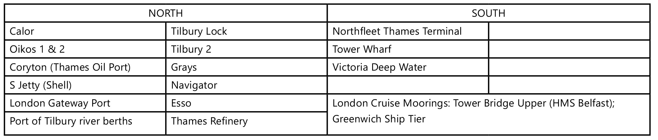
Additional Mandatory Requirements for Specific Berths
Vopak (Navigator)
Both No.1 and No.2 berths require that, in addition to the provisions of the Tug Allocation Tables, vessels of 100m LOA with no manoeuvring aids, and vessels of 128m LOA or 8m draft or above, with any type of manoeuvring aid, require a minimum of one tug.
Oikos 1 & 2
A minimum of one tug is required for all arrivals and departures, beyond which the tug allocation tables apply.
When a vessel is berthed alongside Calor Canvey, an extra tug, in addition to the requirements of the tug allocation tables, is required for head down, ebb tide departures from Oikos 2.
Calor Canvey
A minimum of one tug is required for ebb tide ‘head down’ departures, beyond which the tug allocation tables apply.
Thames Oil Port
A minimum of one tug is required for ebb tide ‘head down’ departures, beyond which the tug allocation tables apply.
Esso no.1 Jetty
A minimum of two tugs is required for berthing, beyond which the tug allocation tables apply.
A minimum of one tug is required for all departures, beyond which the tug allocation tables apply.
Grays 1 & 2 jetties
An extra tug is required, in addition to the requirements of the tug allocation tables, for vessels over 225m berthing or unberthing in southerly winds.
Shell S Jetty
An extra tug is required, in addition to the requirements of the tug allocation tables, for ebb tide ‘head down’ departures.
Tilbury Grain Terminal – Inner Berth
The limited area available to the rear of the Tilbury Grain Terminal jetty restricts the use of tug assistance for ships manoeuvring to and from the Inner Berth. Tug requirements for this berth are as per the table below, for vessels up to 128 metres.
Agents and Masters wishing to arrange for the berthing/unberthing of a vessel of over 128 metres must consult the Duty Port Controller and the Duty River Pilot.
SPECIFIC LOCAL ARRANGEMENTS
London Gateway Port
Assessments for a reduced tug allocation for vessels using London Gateway Port will be undertaken only for vessels less than 320m LOA and/or 13.5m draught. Inbound ULCS’s should make contact with assisting tugs at SR4 and commence Pilot/Tug Master exchange with special reference to the location of picking up tugs lines’ and securing. Unless specified in the Pilot/Tug Master exchange, at least one tug will meet the vessel at Sea Reach 7 and will make fast according to the Pilot’s requirements. In the event communications have not been made at Sea Reach 4, then all tugs for the vessel should assume a Sea Reach 7 rendezvous.
Barking Creek
Some vessels trading to berths in Barking Creek are very close to, or at the physical limits in terms of length and/or draught, which allow a vessel to transit the Creek, manoeuvre and swing safely for the berth. In some cases, these operations require tug assistance.
The use of tug assistance in Barking Creek is necessarily restricted by the confined nature of the area, the draught limitations imposed by the Creek itself and the cill depth of the Barking Creek Barrier.
Access for vessels to and from the Creek is limited to a short period over the high water. For most wind conditions of under Force 5 an attendant suitably (PLA) licensed workboat of 120 horsepower or above is adequate to assist (without connecting a tow line) by pushing in, swinging and manoeuvring. A workboat is of particular help in pushing a vessel away from a berth.
In conditions where a vessel is being manoeuvred in the Creek in a wind of over Force 5 from directions south through to west, and particularly when leaving the Creek stern first, it is strongly recommended that a suitable tug licensed by the PLA as a ship towage tug is employed. Due to depth limitations in the Creek the tug should have a draught of no more than 4.0 metres.
Thames Refinery (Tate & Lyle)
Any vessel sailing from Thames Refinery stern to tide, having a length overall of between 130m and 149.9m, will be provided with an additional tug over and above the Code of Practice Guidelines.
Northfleet Hope Container Terminal – Tilburyness
When a vessel which is berthed head down is departing on a flood tide from the container terminal using tugs and a strong tidal counter flow is present off the berth, it is strongly recommended that the tugs are retained, but not necessarily secured to the vessel, until the vessel has fully entered the stream and safely negotiated the bend.
Tug Assessments
Assessments for Reduced Tug Allocation
If the Berth Owner/Operator is in agreement, a vessel owner/operator whose vessel has good manoeuvring capabilities and characteristics and which regularly visits the Thames, may apply to the Harbour Master to have the vessel assessed to reduce the number of tugs allocated to it under reasonable weather and tidal conditions. The following Berth Owners/Operators are willing to allow Tug Assessments for ships calling at their facility:
- London Gateway Port
- Port of Tilbury river berths
- Tilbury Lock
- Tilbury 2
- Northfleet Thames
- Tower Wharf
Individual vessels will usually be limited to a maximum of four such assessments – one each for flood and ebb tide berthing and unberthing. During an assessment the vessel will have the recommended number of tugs available but the Pilot, with the agreement of the Master, given reasonable conditions and within the bounds of safety, will endeavour to use fewer tugs. He will then submit a report to the Harbour Master on the safety of the operation, including how the vessel handled. Recommendations for future tug allocation will then be based on the outcome of the assessment.
Outcomes of assessment will be reviewed internally by a panel, which includes harbourmasters and pilots, before any decision is made. Outcomes will specify the limiting conditions under which tug reductions apply and will usually be limited to a maximum of 20 knots wind.
Applications for a reduced tug allocation assessment must be made in writing, by email to the Harbour Master ([email protected]) who, subject to agreement by the Berth Owner/Operator, will arrange for the nominated vessel to be assessed - generally on its next visit, subject to a suitable assessing pilot being available.
Maximum Reduction in Tug Allocation
Any vessel that has already been assessed and had a tug reduction approved will not be assessed for a further reduction in tug allocation, except in exceptional circumstances and if a highly manoeuvrable vessel, and as agreed by the Harbour Master and the Berth Owner/Operator.
Tug Assessment Validity
Tug Assessments will be valid for up to five years, but no longer than three years from the vessel’s last visit to the port. At that point a new tug assessment will be required.
Where a vessel that has a reduced tug allocation undergoes any significant changes to its manoeuvring ability, the assessments will become invalid. Further assessments may be undertaken for the new vessel configuration.
Sister Vessels
Tug Assessments are valid for individual vessels. Sister vessels will normally be required to have their own assessments.
SECTION TWO
USING THE TUG ALLOCATION TABLES
Step 1
Turn to the appropriate Part (A-D) dependent upon the destination or departure berth and/or the vessel type and size.
Step 2
Using Table 1, identify the Ship Type Code as defined by the vessel’s length overall and draught.
Step 3
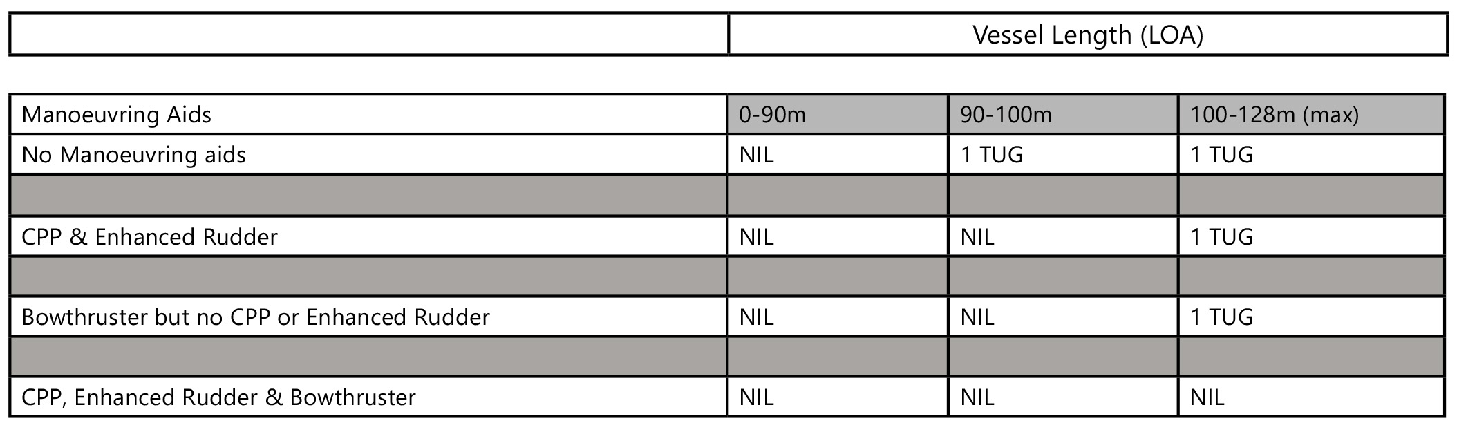
Take the Ship Type Code from Table 1 and the vessel’s operational manoeuvring aids to establish the Manoeuvring Aids Allowance Code in Table 2.
Step 4
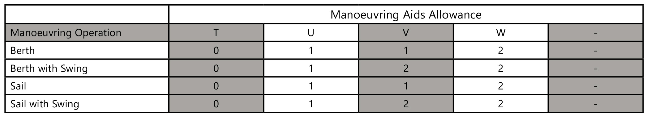
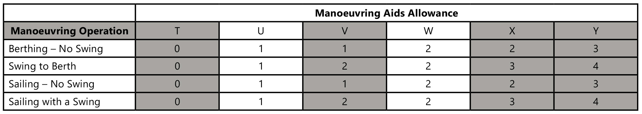
Table 3 will then identify the number of tugs required as defined by the Manoeuvring Aids Allowance Code and the nature of the manoeuvre.
Step 5
Where relevant, Table 4 provides an augmentation to towage requirements due to wind conditions. Part E provides an estimated allowance for windage and also a useful formula for calculating the bollard pull required in varying wind strengths.
Note:
In addition to the number of tugs required, there is also a minimum Bollard Pull (BP) requirement for some berths/scenarios. The declared BP for tugs licensed for ship towage on the Thames can be found here.
An allowance of +- 3% may be applied to the published BP when using these tables.
Where 2 or more tugs of a specified BP are required, tugs within 5% of the required individual BP may be used, as long as the combined BP is met. E.g. where 2 tugs of 80t BP are required, the combined BP requirement is 160t (2x80t). This may be achieved with one tug of 76t (80-5%) as long as the second tug has a BP of at least 84t.
SECTION THREE
TUG ALLOCATION TABLES
PART A - RIVER BERTHS: LONDON BRIDGE TO SEA REACH No.7 BUOY
Table 1 - SHIP SIZE CODE
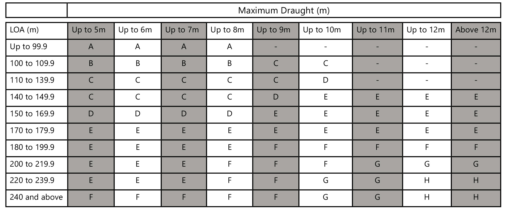
TABLE 2 - MANOEUVRING AIDS ALLOWANCE CODE
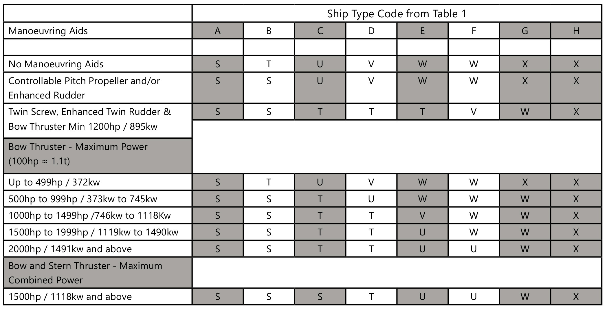
TABLE 3 - NUMBER OF TUGS REQUIRED
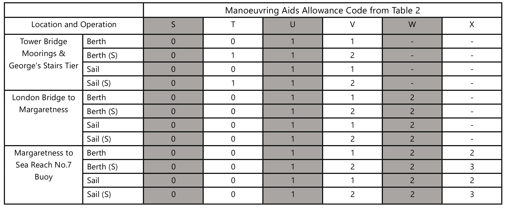
Notes:
1. (S) = Swing necessary or manoeuvring stern to tide.
For vessels over 180m swinging into the West India Dock Bellmouth and backing up to Greenwich the Harbourmaster must be consulted to determine the tug requirement. A minimum of 2 tugs will be required.
2. Tug allocations for ships over 200m LOA navigating above the Thames Barrier are subject to the requirements identified in the associated risk assessment(s). The Harbourmaster must be consulted in such cases.
3. See "Additional Mandatory Requirements for Specific Berths" above for additional requirements at Thames Refinery, Navigator and Oikos.
PART B - NORTHFLEET HOPE CONTAINER TERMINAL
TABLE 1 - SHIP SIZE CODE
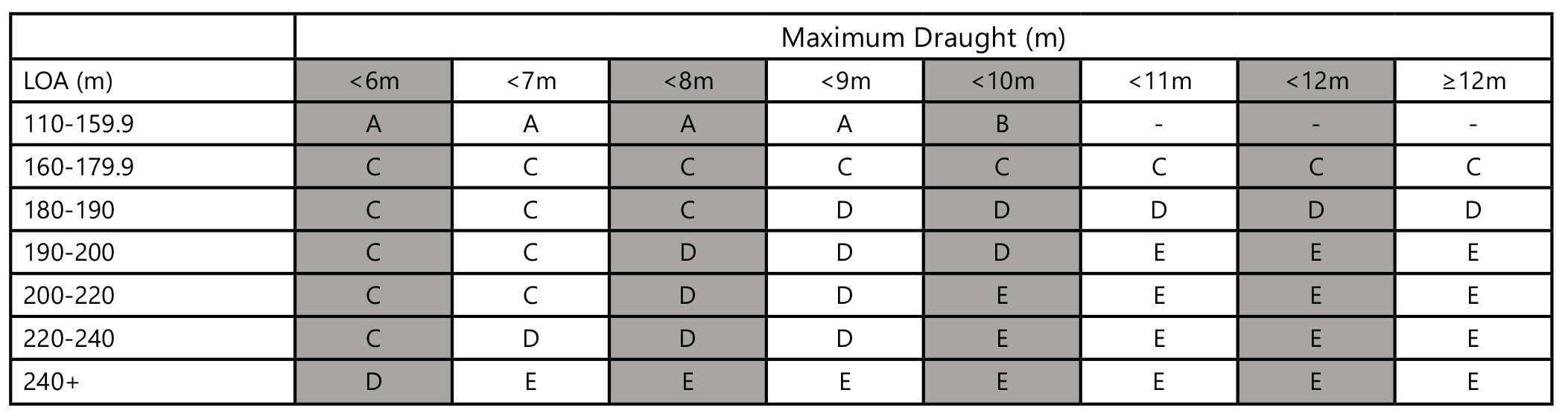
TABLE 2 - MANOEUVRING AIDS ALLOWANCE CODE
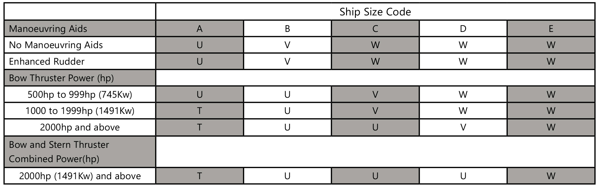
TABLE 3 – NUMBER OF TUGS REQUIRED
This table is based on the requirement for each tug to have a minimum tug bollard pull of 50 tonnes.
Additional towage requirements
For any vessel, an additional tug may be necessary in circumstances where the vessel is required to manoeuvre stern to tide or in high wind conditions (See also Table 4 below) and must be considered as part of the dynamic risk assessment at the time.
For vessels over 225m LOA and/or 10m draught, an additional tug will be required for berthing stern to tide on the Upper or Lower berths.
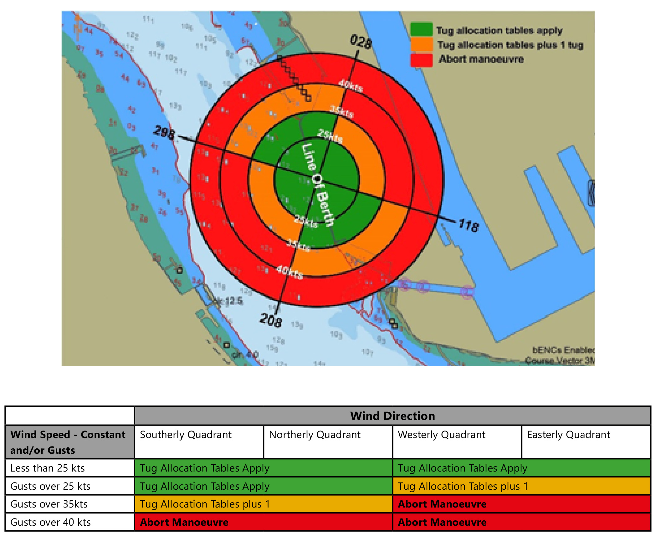
TABLE 4 - AUGMENTATION OF TOWAGE REQUIREMENT DUE TO WIND CONDITIONS
PART C - TILBURY LOCK
TABLE 1 - SHIP SIZE CODE
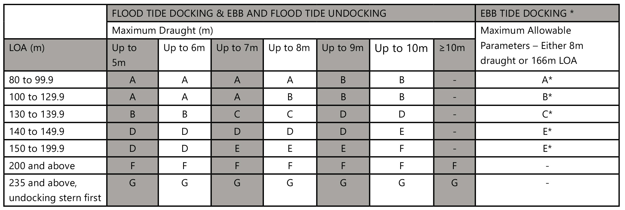
Note: *Agents and Masters arranging tug allocation for Ebb Tide Docking must consult the Duty Port Controller before final arrangements are made.
TABLE 2 – MANOEUVRING AIDS ALLOWANCE CODE
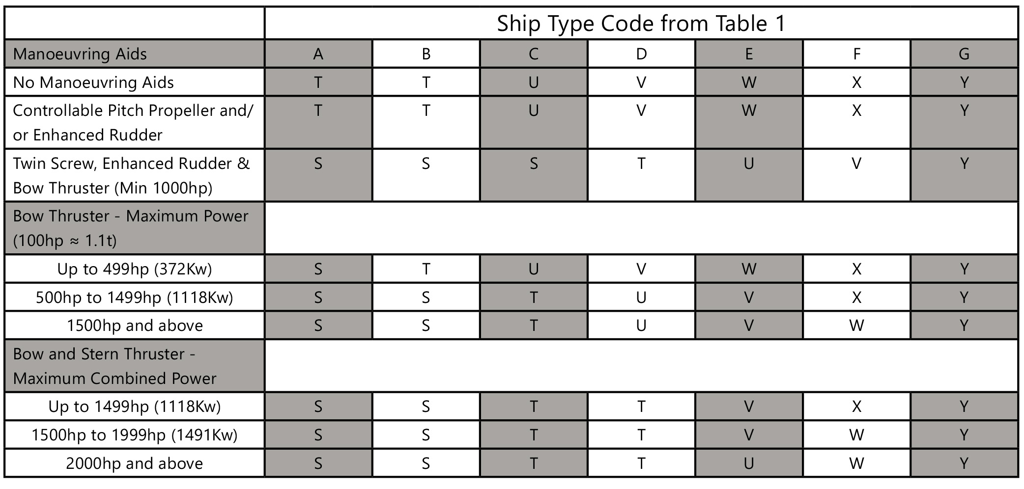
TABLE 3 - NUMBER OF TUGS REQUIRED
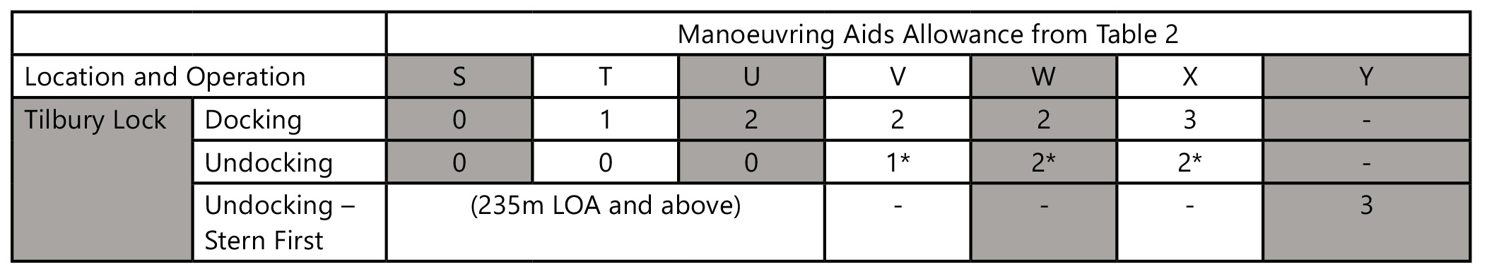
Notes:
1. * The PLA Duty River Pilot must be consulted before the Master or Agent arranges the sailing of a vessel exceeding 185m LOA or 29m beam on an ebb tide.
PART D - LONDON GATEWAY PORT
TABLE 1 - SHIP SIZE CODE
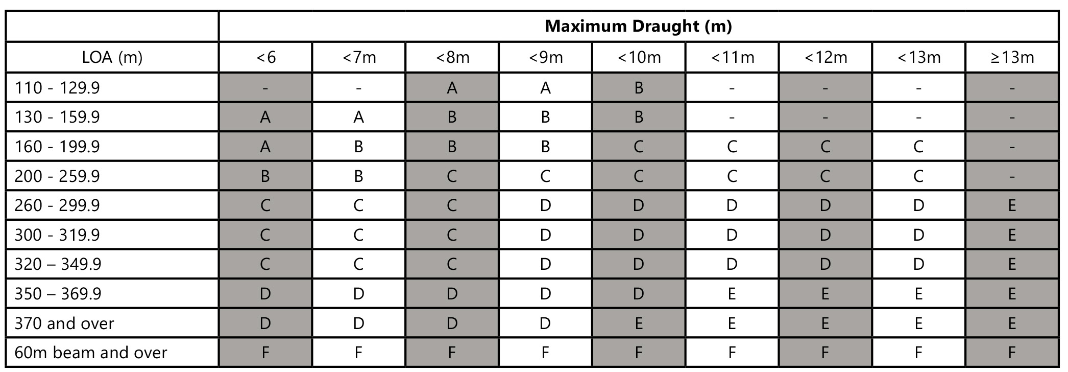
TABLE 2 – MANOEUVRING AIDS ALLOWANCE CODE
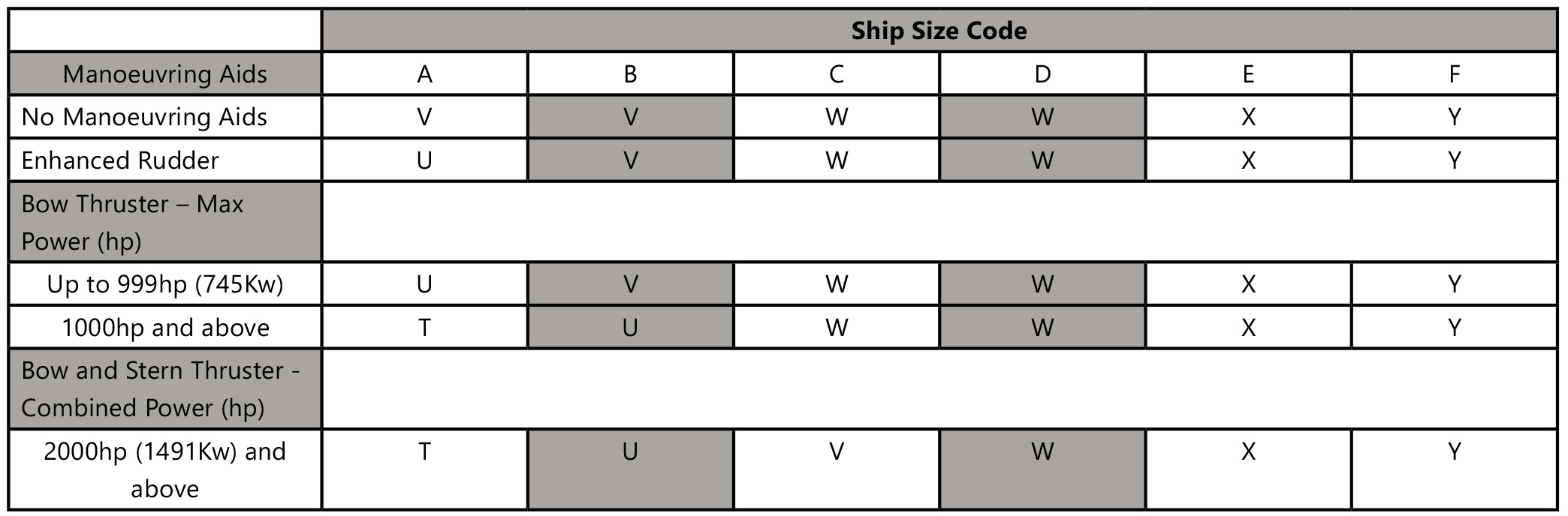
TABLE 3 – NUMBER OF TUGS REQUIRED
Notes:
1. This Table is based on the requirement for each tug to have a minimum bollard pull, as follows:
a) for vessels up to 250m LOA and/or 12.0m draught, 60 tonnes bollard pull;
b) for vessels up to 320m LOA and/or 13.5m draught, 60 tonnes bollard pull; and
c) for vessels over 320m LOA and/or 13.5m draught, 80 tonnes bollard pull.
d) for vessel of 60m beam or more three tugs of 80 tonnes bollard pull. Where a 4th tug is required it should be at least 70 tonnes bollard pull.
2. An additional tug may be necessary in circumstances where the vessel is required to manoeuvre stern to tide or in high wind conditions (See also Table 4 below) and must be considered as part of the dynamic risk assessment at the time.
3. For vessels over 320m LOA and/or 13.5 or 60m beam or more, where an extra tug is required, in addition to the table requirements above, that tug should normally have a minimum BP of 70 tonnes.
TABLE 4 - AUGMENTATION OF TOWAGE REQUIREMENT DUE TO WIND CONDITIONS
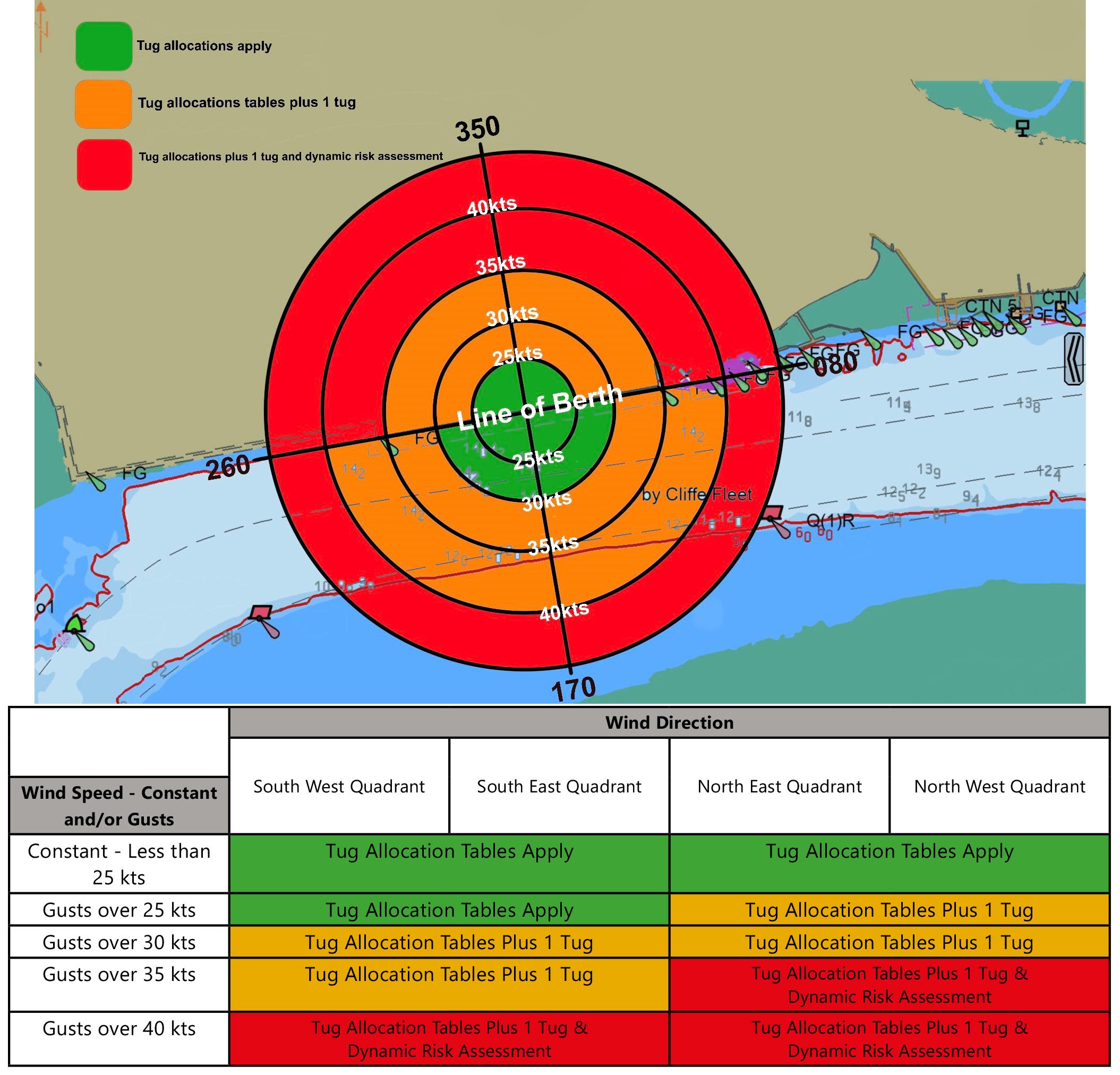
Note: Subject to the conditions at the time and the size of the vessel involved, the decision to continue with the manoeuvre will be determined by the associated dynamic risk assessment and will involve all relevant parties i.e. the Master, Pilot, Duty Port Controller and the Berth Operator.
PART E - ALLOWANCES FOR WIND
The master of any container ship greater than 250m in length is required to submit the CALCULATED LATERAL WINDAGE AREA for their vessel. This will allow the pilot of the vessel to adequately assess the towage requirements in advance of boarding and dynamically risk assess the intended manoeuvre for higher winds.
The formula below can be used to calculate the total lateral windage force in tonnes for a vessel in varying wind strengths.
Lateral windage force (tonnes) = 0.065 x A x V2 /1000
With 25% safety margin = 0.08 x A x V2 /1000
Where:
- A is the wind area of the vessel in m2; and
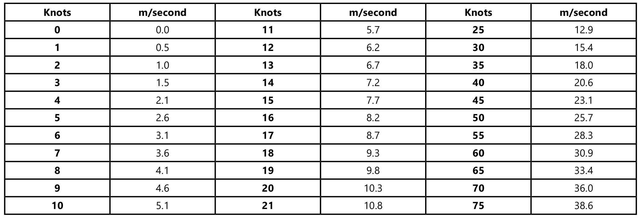
- V is the wind speed in m/sec
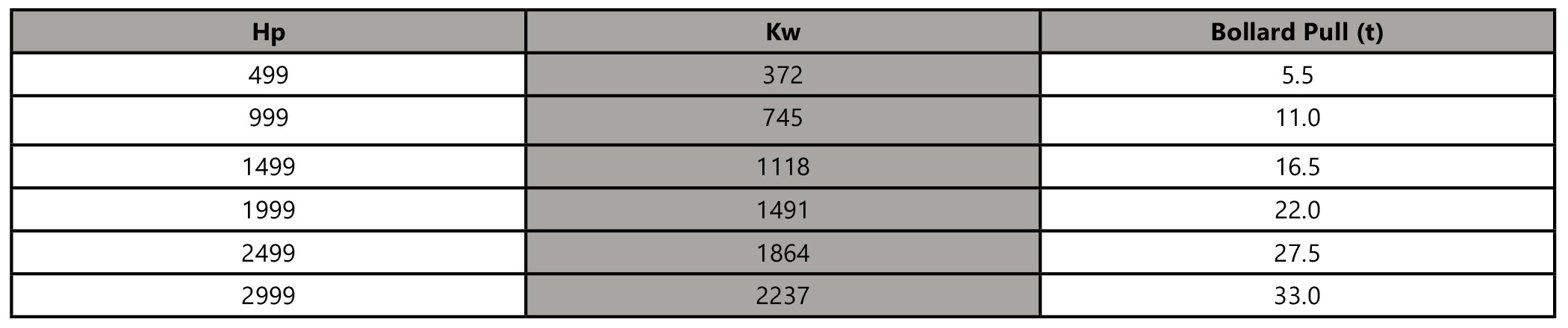
PART F – Hp / Kw CONVERSION TABLE (approximate):
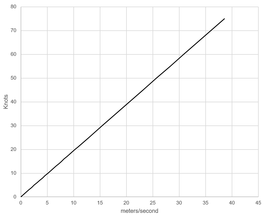
Knots – m/s CONVERSION TABLE: